You need a new formula for success when abutting incompatible materials.
Liquid-applied waterproofing membranes are popular for waterproofing exterior balconies and corridors. The purpose of the membrane is to keep water from contacting the moisture-sensitive structural elements and from migrating to the finished interior space. A common notion is that you should terminate liquid-applied membrane decks in the same fashion as sheet-good roof and waterproofing materials—with metal. Metal drip edges are often placed along the perimeter of a corridor or balcony deck to be covered with the deck-coating material. Similarly, light-gauge metal angle (commonly referred to in the roofing world as 5 by 5) is positioned along deck-to-wall interfaces so that workers can apply the deck coating over its surface. The elevated deck surface is typically plywood, concrete or cement fiberboard.
The use of metal flashing gives most professionals a feeling of comfort because of its long, uninterrupted and impossible-for-water-to-penetrate, solid cross-section. The reality, however, is that metal flashings is sold in pieces that you must lap, abut, bend and cut. Perhaps the greatest concern with metal flashing is that the liquid-applied membrane must transition from the horizontal flange of the flashing to the deck substrate. When the metal flashing moves—due to the result of thermal strain, discussed in the next section—the membrane interface becomes highly stressed and tears.
The Effect of CTEs
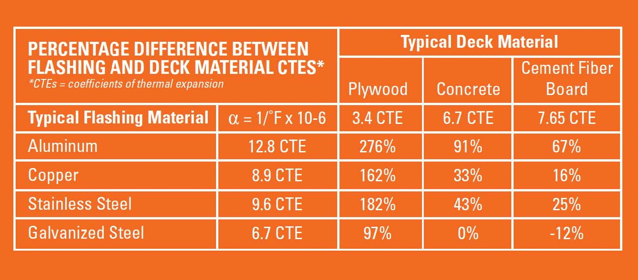
To understand the complexity of how thermal strain affects a project, consider its trigger: temperature. Heat causes materials to expand, while cold weather causes them to contract. How the variances in heat and cold affect material is reflected in their coefficient of thermal expansion (CTE). CTEs characterize the rate at which the material will expand or contract during a unit change in temperature. A review of metals commonly used for flashing (aluminum, copper, galvanized steel and stainless steel) reveals that aluminum changes at the greatest rate, followed by copper, stainless steel and galvanized steel. (See the table for typical CTEs of deck substrates compared to flashing materials).
The differences in material-expansion change can be substantial between the substrate and the flashing. The most significant difference is between aluminum flashing and plywood decking, in which the flashing has a strain rate that is nearly four times greater than its substrate. Notably, galvanized steel and concrete have the same CTE.
CTEs Affect Fasteners, Too
Typically, the flashing metal is secured to the deck with screws or nails. The problem with this technique is that these fasteners inhibit the flashing material's ability to expand and contract. The consequence? When it gets hot, the flashing will "arch" between the fasteners as it attempts to alleviate its thermal elongation. Due to fastener restraint, the material creates "waves" that allow the material to elongate upward without actually increasing its end-to-end length. This phenomenon is commonly referred to as "oil canning" (see Figures 2a and 2b). When it occurs, it causes the liquid-applied membrane to tear where it bridges from the deck onto the metal flashing because it is so tenaciously bonded to both the deck and the metal. Elongation of the fastener holes also can occur when the metal flashing expands.
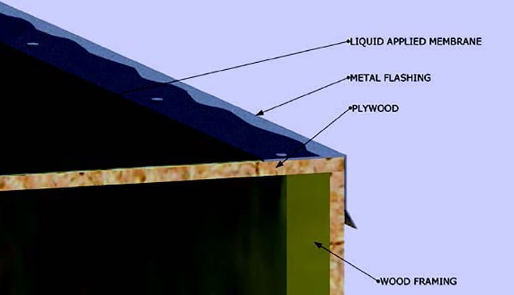
Figure 2a
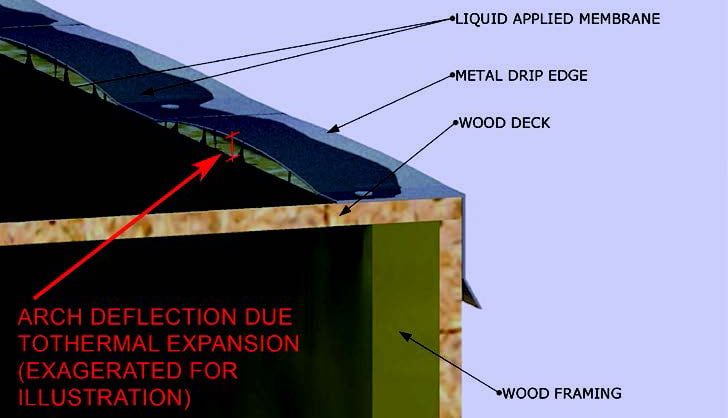
Figure 2b
One of the best ways to illustrate the incredible effect of thermally induced expansion is using one of my favorite structural-engineering examination questions: A 100-yard-long segment of railroad track is construction in the middle of winter in 30° F weather. It is fixed in place at the ends with bolts and left unrestrained along the remainder of its length. Once summer arrives, how high will the track arch when temperatures reach 100° F? Students are typically astounded by the answer. While the track expands little more than an inch and a half, the vertical height of the resultant arch is an incredible four feet (see Figure 1 below).
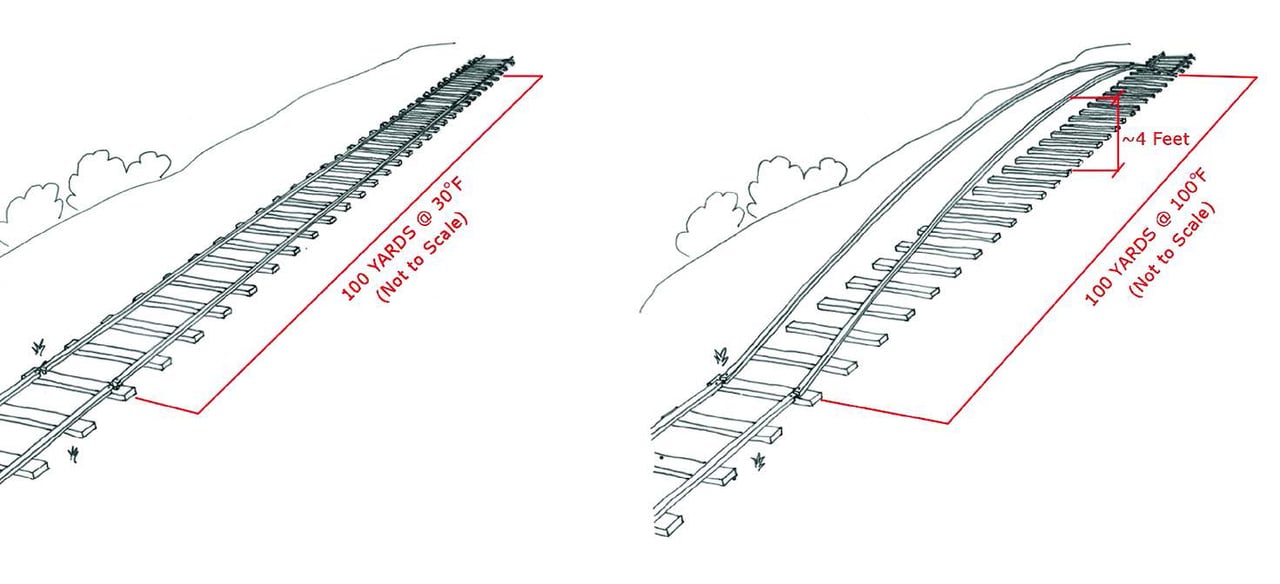
Figure 1
As a practical matter for this discussion, what is the resultant height of an induced arch installed under the following circumstances:
- A 20-foot-long piece of aluminum flashing
- Applied over a wood deck
- Secured only at its ends
- Experiencing a 100° F temperature change
The answer? Five inches!
Typically, edge metal is secured with nails spaced about 12 inches on center. The resultant arch between fasteners spaced at 12 inches is 0.225 inches (nearly one-fourth of an inch). This vertical offset movement is far greater than what can be bridged even with the most elastic deck coatings. Therefore, most deck-coating manufacturers would not recommend bridging dissimilar materials without a backed sealant joint. Unfortunately, the provision of a properly backed joint at this flush-material abutment is not possible. Even if it were, the movement described is beyond the capacity of many sealants.
On the other hand, flashing metal installed during the hot season will contract once winter arrives. This will cause elongation of the fastener holes securing the fasteners, potentially creating voids in the membrane that may tear to accomodate significant movement.
It should be acknowledged that the installation of metal flashings will probably not be installed during the coldest or hottest times of the year. Therefore, the thermal strain effect may not be as significant as described above. Nevertheless, the examined temperature variation of 100° F is likely conservative, as it accounts only for typical ambient temperature fluctuations. In direct sunlight, the surface temperature of metals will increase significantly above the ambient temperature.
Some contractors choose to solder or weld segments of abutting flashing together. Don't do it! The flashing will collect the induced temperature strains of the individual segments and combine them into a continuous piece, thus multiplying the strain effect.
The conclusion is that materials with similar CTEs should be used for liquid-applied membrane substrates and flashings with similar CTEs. As the table shows, it is a mistake to incorporate metal flashings with a wood deck substrate. However, regardless of material, the flush joint that naturally occurs between a deck and metal flashing is problematic.
The Best Solutions to Avoid Failure
The best chance for liquid-applied membrane success is to use the same material as a substrate for the deck, wall and drip edge. Though contrary to conventional though, it is less risky to extend a deck coating from a wood deck onto the adjacent wood-sheathed wall—with a properly backed sealant joint at the intersection—than it is to extend it onto metal flashing. An even better solution is to use reinforced cement board as a substrate for both the deck and wall sheathing to which a liquid deck coating will be applied. Cement board is not subject to hygroscopic shrinkage (loss of water), is inorganic and, therefore, not subject to deterioration. Plus, you can use cement board wall backing in conjunction with a concrete deck.
If possible, simply avoid the use of metal along the outer membrane edge. Admittedly, metal flashings will likely be the only feasible means to achieve some deck-edge terminations. For example, you can't avoid making diverter (kick-out) flashings at deck terminations to wall interfaces (see Figure 3 and 4 below).
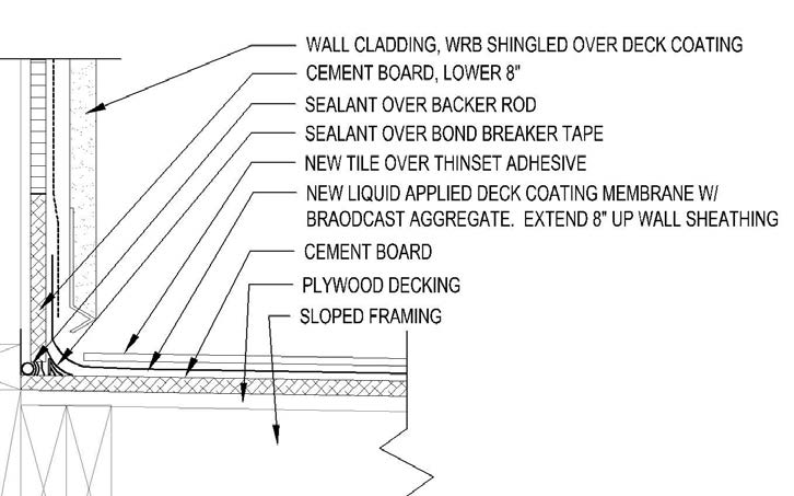
Figure 3
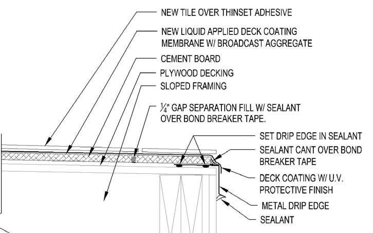
Figure 4
If metal terminations must be used, configurations should be examined that would allow for properly profiled and backed sealant joint to bridge the dissimilar deck and flashing material interface. If a concrete topping or cement board is used, consider placing the metal drop edge under the concrete or deck sheathing, so that a vertically backed joint can be provided between the abutting materials.

Brett Newkirk, P.E.
Principal Engineer, Alta Engineering Company
Brett Newkirk is a practicing structural engineer with Alta Engineering Company (Jacksonville, FL). He specializes in the diagnosis and repair of moisture-affected structures. You can be contact him at: brett@altaengineeringco.com