INTRODUCTION
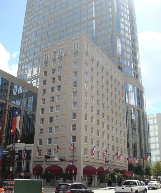
The historic Lancaster Houston Hotel, located in Houston, TX, is a twelve-story structure
built in 1926 (Fig.1). Originally known as “The Auditorium Hotel,” the Lancaster was designated a Recorded Texas Historic Landmark by the Texas Historical Commission (THC) in 1984.
CONDITION ASSESSMENT
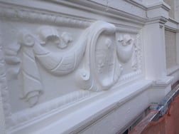
Exterior wall evaluations were performed in phases for several years and different types of distress conditions were identified. The most significant deterioration occurred on the top level of the structure on the south and west elevations. Typical observations included cracks at the spiral columns and mortar joints, localized surface spalling of cast stone 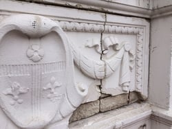 trim and spandrel panels (Fig. 2) and missing ornamental cast stone spiral columns and brackets.
Based on our conclusions, we recommended sealing facade cracks greater than 0.012 inches (0.3 mm) in width, repairing localized cast stone and masonry spalls in the facade and removing deteriorated cast stone units to replace them in kind. The cast stone replacement encompassed a total of 28 column and bracket units and 14 spandrel panels. The focus of this article is on the spandrel panel cast stone replacement.
RESTORATION PLAN
Original construction documents were not available for this building, which made the cast stone replacement even more difficult. Without any details, our only option was to make a mold out of the physical cast stone ornaments. We proposed two methods to the contractor to create the molds. First, the conventional approach which required vertical access to the facade, removal of a spandrel panel, column and bracket in good condition and, finally, manufacturing the molds. This method, although tried and true, is costly and comes with the inherent risk of damaging the delicate cast stone features. The second method proposed was to use 3D scanning and modeling technology to create a three-dimensional model of the architectural features and use the model to create a negative mold or a master copy. This method removes the risk of damaging a cast stone piece in good condition.
Given that the contractor had already mobilized on site, a combination of both methods was selected to manage risk and costs. This involved manufacturing traditional molds out of physical spiral column and bracket samples (due to their small size) and creating non-traditional molds from 3D models for the delicate 60 x 22 inch (1524 x 559 mm) spandrel panels. We evaluated different methods to create the 3D model and determined that photogrammetry was the most cost-effective and practical method.
Photogrammetry is the science of making measurements from photographs. In short, computer algorithms attempt to identify points in common between a set of photographs and plot them in a three-dimensional space (i.e. a point cloud). Once the point cloud is created, a mesh which connects all the individual points with flat planes can be generated using traditional modeling software. A 3D mesh allows an engineer to manipulate its dimensions and shapes, analyze the object for stresses and strains, 3D print the model or use a computer numerically controlled (CNC) mill to create our shape. The main advantages of photogrammetry include this method being extremely portable and only requiring a camera, a trained photographer and a computer modeler.
DEVELOPING THE 3D MODELS
The general procedure was as follows: While on the suspended scaffold, hundreds of photographs were taken of the spandrel panels, columns and brackets using indicator 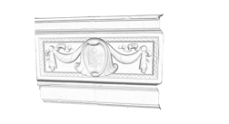 targets in the objects so the photogrammetry software is able to recognize similarities between photographs. The photographs were then manually sorted to delete photographs that were either blurry or not part of the data set needed. Once sorted, the photographs were uploaded to a commercially available photogrammetry software package to process the point cloud. Once processed, the point cloud was imported to a free and open-source 3D modeling software in order to create a solid surface mesh that connects all of the points in the point cloud (Fig. 3). The time it takes to process a mesh is highly dependent on the complexity of the geometry and the density of the point cloud. For reference, the decorative spandrel took approximately three hours to generate the point cloud, one hour to mesh and three hours to edit the model and complete the final touches.
As a trial, we used 3D printing to determine if the models were detailed enough for full scale production. A partial model of the nspiral column and capital was generated, edited and printed using a MakerBot 3D printer and biodegradable thermoplastic aliphatic polyester filament, commonly known as PLA. The result was a miniature version of the 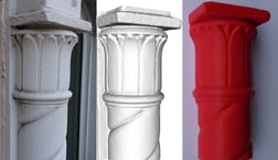 column with all its surface defects and details (Fig. 4). Pleased with the results, it was time to move forward with the full scale replica of the spandrel panel.
DESIGN OF CAST STONE SPANDREL PANELS
Matching the existing features of the existing spandrel panels required using cast stone as our final product. Cast stone, as defined by the Cast Stone Institute, is a refined architectural concrete building unit manufactured to simulate natural cut stone. The materials and processes used in the manufacturing of the stone depend on the required appearance and physical properties. Our specifications required producing cast stone with a minimum 28-day compressive strength of 6,500 psi (44.8 MPa), a 28-day absorption rate ranging between 6% to 8% and shrinkage not to exceed 0.065%. Additionally, the cast stone was to be reinforced using either non-corrosive reinforcement or welded wire fabric with a minimum reinforcement of 0.25% of cross sectional area.
The existing cast stone spandrel panels are supported by a steel shelf angle connected to the building frame with post-installed anchors and are laterally supported by corrugated metal ties. For the replacement panels, we utilized the same steel shelf angle to support the gravity loads and secured each panel with four new stainless steel post-installed chemical anchors to resist lateral wind loads. The chemical anchors were detailed to be installed at an angle of 15 degrees from the horizontal plane to provide a mechanical interlock between the anchor and the cast stone spandrel.
FABRICATING THE SPANDREL PANELS
The method used to create the molds was CNC low-density foam to form the shape, create a rubber mold and then use cast stone to create the spandrel. This method offers relatively low costs, ability for the contractor to cast their own units and the improved durability provided by cast stone over polyurethane-coated high density foam.
A StereoLithography (STL) file was exported and sent to the manufacturer. This file format is widely used for rapid prototyping, 3D printing and computer-aided manufacturing. Using a three axis CNC machine, a foam master copy of the spandrel panel was milled and sanded. The final master copy coated with polyurethane was delivered to the project site ready for the mold-making process.
 Molds made of liquid urethane were fabricated from the master copy. The cast stone panels were fabricated at a plant using the master copy, delivered to the site and installed (Fig.5).
CONCLUSION
The distressed spandrel panels were successfully replaced with new cast stone panels that closely match the shape, size, texture and color of the original cast stone panels maintaining the historic significance of the building. Based on this project experience, we are confident that photogrammetry can be implemented in any project requiring replacement of ornate or historical building features without the risk of damaging the existing conditions of the facade and at the same time reducing design and construction costs.