By Michael S. Plewacki, Principal/Facade Engineering Manager
Mid-century through 1980s buildings with lock-strip or “zipper-gasket” glazing systems are an ever present part of the urban landscape in many cities across North America. Although these systems are considered outdated by many and seldom used in new construction, the systems have performance attributes that should merit respect.
For many in the facade community, lock-strip gasket facades are often dismissed as a system to be removed and replaced with modern aluminum curtain wall. While this may be practical in certain situations, it is far from the only option available and not always the right option for the owner’s budget or maintaining the original architecture of a building.
Lock-strip facades continue to endure, but age has taken its toll on the functionality of what was once a revolutionary glazing system. By maintaining the lock-strip gasket facade and upgrading glazing when possible, building performance can be restored or even increased as retrofit technology improves.
Remedial options are available for lock-strip gasket facades that focus on

preserving and maintaining the primary elements and appearance of the system from simple remediation efforts, such as the installation of exterior “wet-seals” to limit air and water infiltration, to complete replacement and reglazing. (Fig.1 and Fig. 2)
Improved curtain wall performance (reduced air infiltration, lowered solar heat gain and improved acoustical performance) is achieved by introducing modern insulating glass with a low-e coating and emerging technologies, such as vacuum insulating glass (VIG), and presents possibilities for replacement of an original monolithic glazed system for increased energy performance.
Reglazing also provides the opportunity to increase spandrel insulation or change the aesthetic of the facade by introducing (or removing) existing spandrel panels.
While the benefits of the above are appealing, lock-strip gasket replacement projects are not immune to challenges. As with most remediation projects, there are technical considerations to address.
INTRODUCTION
One of the first large scale lock-strip gasket glazing projects was completed in 1952 at the General Motors Technical Center in Warren Michigan by Architect Eero Saarinen & Associates. In 2000 the building was listed on the National Register of Historic Places and in 2014 it was designated a National Historic Landmark.
In 1974 C.J. Parise made mention of this building’s facade system in his paper “Evaluation and Test of Lock-Strip Gasket Glazing Systems” in the American Society for Testing and Materials (ASTM) Special Technical Publications 552 where he concluded:
“There have been many successful (lock-strip) installations in the past 20 years which are still providing satisfactory service. Lock-strip gasket glazing is an excellent glazing system, but as true of any building system, there are certain precautions which must be observed for optimal performance.” (Parise et.al, 1974)
Although he did not live to see the GM Tech Center become a National Historic Landmark, his conclusion on this topic is as true today as it was in 1974 and concisely summarizes the wide range of challenges associated with working with lock-strip gasket glazing systems.
Since the 1974 article, the technology of the lock-strip gasket has largely remained the same. However, modern lock-strip gasket designs have improved based upon early research and testing as well as improvements in manufacturing technology. As industry processes and the body of technical knowledge have evolved, so have the standards governing the properties, installation and glazing of these systems.
Technical standards are well documented and are a readily accessible resource to gain perspective where the “experience factor” of someone who has specific working knowledge of these systems, such as C.J. Parise in the 1970s and those like him of that era, becomes less available.
To effectively remediate and replace lock-strip gasket systems, a team must understand not only the applicable standards but also the lessons learned and documented by product manufacturers and those with experience if lock-strip glazed buildings are to stay relevant in our time.
BACKGROUND
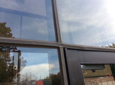
Lock-strip gaskets or “zipper gaskets” are generally described as a two-part neoprene gasket assembly consisting of a main body gasket, which is used to capture and support the glazed infill, and a lock-strip or “zipper” that is inserted into a receiving channel on the main body gasket to provide compression between the main body gasket, glazing infill and framing. Lock-strip gaskets provide a complete thermal break from the frame of the building and glass to assist in providing an efficient envelope. With no exposed metal, the systems provide exceptional condensation control as well as exceptional vibration and noise dampening (Griffith Rubber Mills, 2010).
Remediation of a lock-strip gasket curtain wall system, including removal and replacement of the lock-strip gasket curtain wall and glazing, is an option for consideration in many cases where preservation of the building facade is desired.
In such cases, it is likely the lock-strip gasket will require full replacement due to the existing condition of the gasket material. This is highly dependent on the age and exposure of the materials, but the majority of projects considering reglazing have aged to the point where replacement is a prerequisite. However, there are times when this may not be necessary and a waterproofing remediation can be undertaken.
During a reglaze and gasket replacement project, there is an opportunity for the existing aluminum framing system seals (internal/perimeter), as well as coatings, to be restored and the system structurally modified to accept modern high performance glass.
Improvements may include dual-paned insulating glazing unit (IGU) as infill, as well as increased spandrel insulation. The aesthetic of the facade can be altered by introducing (or removing) metal spandrel panels. As the technology becomes more commercially viable, there is the opportunity to reglaze with vacuum insulating glass (VIG) for projects where the modification of a monolithic glazed system is prohibitive and increased energy performance is desired.
Introducing a new lock-strip gasket system to an aged facade with modern low-e coated insulating glass can provide additional visible light transmittance, lower solar heat gain and improved sound transmittance (OITC and STC) performance. This all translates to increased interior occupant comfort and safety, as well as energy savings.
LOCK-STRIP GASKET REMEDIATION
As previously mentioned, remediation of a lock-strip glazing system should include an evaluation of the current physical condition for structural performance, as well as an evaluation of air and water infiltration. Depending on the findings of this evaluation, a remediation of the existing lock-strip gaskets could be considered to maintain the serviceability of the facade.
There are several elements of a lock-strip gasket system remediation that may be considered to extend the serviceability of the existing glazing system. Generally, a remedial program will employ a strategy of mechanical stabilization and preservation of the existing gasket, as well as a means of reducing air and water infiltration.
REINFORCEMENT CLIPS
To provide structural support of the existing system, a remediation may include installation of retaining clips at exterior horizontal and vertical lock-strip gaskets. The addition of mechanically attached retaining clips will help to ensure structural performance of the system as deteriorated gaskets may not exhibit the same performance characteristics as originally designed. This is especially important at corner zones and locations anticipated to have significant wind exposure. (Fig. 3)
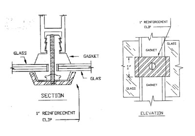 The use of reinforcement clips results in an increase in the resistance of the gasket to roll off the frame. The use of one clip per side provides substantially higher load capacity and still greater capacity is obtained using two clips per side.
Depending on the gasket and frame profile, several reinforcement clip options are available. The majority of applications require an exterior installation, but interior clips are used for some systems to augment exterior clips.
The project-specific reinforcement requirements for the lock-strip gasket system should be designed by a Professional Engineer with experience in facade engineering evaluations. The engineer will be able to determine the number of clips and spacing requirements as well as evaluate the profile of the clip to ensure glass to metal contact is avoided. The clip design strategy can then be coordinated with any remedial waterproofing work.
SEALANTS
To provide reduced air infiltration and increased water penetration resistance, an aged lock-strip gasket system may be sealed along the exterior of the gasket. This work generally includes installation of new silicone “wet seals” between the lock-strip gasket and the exterior glass at all perimeters and “bridge seals” at gasket splices and at transitions such as the welded corners of the extrusion.
Typical wet seals consist of a bead of neutral cure silicone sealant tooled between the gasket and the exterior surface of the glass. These joints are tooled to a triangular fillet profile to seal the gasket to the glass. Typical bridge seal work at gasket splices and transitions is intended to seal voids and cracks at the exterior of the gasket. These seals are generally tooled silicone sealant installed with a profile of ½ inch to one inch of sealant adhesion surface and a flat thickness of ¼ inch. Generally, black neutral cure sealants are used in these applications due to potential staining of the sealant from contact with the aged gasket and to mask the repairs.
COATINGS AND COVERS
Along with installation of remedial sealants the exterior lock-strip gasket system may be coated with silicone elastomeric coating or covered with extruded silicone sheet to lessen the exposure of the gasket rubber to additional weathering.
Silicone sealant manufacturers whose products are generally used for wet seal and bridge sealant work offer silicone elastomeric coatings generally used for painting opaque exterior walls. These coatings have been used with success on exterior lock-strip gasket applications. Coating the gaskets with a silicone elastomeric provide benefits such as encapsulating the gasket to reduce carbon black and other contaminants from staining glass and adjacent finishes, as well as protection from UV to slow the degradation of the rubber.
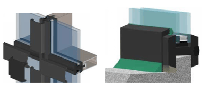 Another option in covering existing lock-strip gaskets is to use preformed extruded silicone sheet membrane. Silicone sealant manufacturers have developed products specialized for this application and include shape profiles that accommodate wet seal installation at glass perimeters and gasket corner conditions. Silicone sheet covering of the gasket system is generally more costly than coating with silicone elastomeric, but there are additional benefits to take into consideration. (Fig. 4)
The silicone sheet membrane is advantageous from a long term performance and durability perspective, and since the product is available in various colors this gives the building owner the ability to change the aesthetic of the facade. In addition, the profile of the extrusion makes it possible to encapsulate gasket reinforcement clips to improve the appearance of the facade.
Other options available include the addition of new aluminum trim color caps installed as part of a lock-strip gasket wet seal remediation. These would be similar to the silicone sheet products in the resulting aesthetics, however they are generally attached by mechanical means using a retaining clip system similar to that used to secure the system but with a modified profile that would accept an aluminum cover cap.
LOCK-STRIP GASKET REPLACEMENT
When replacing gaskets, it is critical to understand that RMA (Rubber Manufacturers Association) tolerance for the production of rubber products, including lock-strip gaskets, is not the same as the tolerances used in the production of glass and insulating glazing units. Tolerance in rubber product production is based on the degree of reproducibility of given dimensions. There are many factors that affect molded rubber products, and these differ from that generally seen in glass production.
RMA has developed tolerance tables with ranges to provide communication between user and provider across a wide range of industries. RMA standard cross-sectional tolerances are established for measurement of outside diameters, inside diameters, walls, width, height and general cross-sectional dimensions of extrusions. Tolerance for each class of material is generally outlined in table format by RMA. As gasket size in each category increase, so do acceptable tolerance ranges.
ASTM C542 “Standard Specification for Lock-Strip Gaskets” establishes minimum dimension for thickness and cross-sectional tolerance of lock-strip gaskets. The basis measurements are derived from reference to RMA Class 2 tolerance. Likewise, standards established by the IGMA (Insulating Glass Manufacturers Association), such as those outlined in TR-1200 “Sigma Voluntary Guidelines for Commercial Insulating Glass Dimensional Tolerances” as well as ASTM C1036 “Standard Specification for Flat Glass”, are often referenced in glass manufacturing. Additional more stringent tolerance requirements may be held by the IGU manufacturer, and these can vary.
The disparity between the glass and rubber tolerance can be an issue during gasket replacement and reglazing. It is recommended that the design of the gasket system be coordinated to accommodate these tolerances so that the system will be able to achieve specified performance within the dimensional range.
Issues of tolerance are not, however, limited to production. Rubber gaskets are susceptible to distortion, shrinkage and environmental factors, so it is critical that consideration be made for these factors early in a project. It is important to have conversations with supplier regarding production tolerance and to review gasket shipping and storage as part of the preconstruction process.
Although gasket design tolerance may be adequate, quality control protocols must be established to ensure the permissible tolerances for the gasket physical properties and dimensions. Critical dimensions such as channel width and depth should be verified prior to gasket installation to ensure glass bite, edge clearance and lip pressure will be maintained.
Installation procedures for lock strip gaskets are outlined in ASTM C716 “Standard Specification for Installing Lock-Strip Gaskets and Infill Glazing Materials.” This specification includes detailed descriptions of the installation of the system including inspection, preparation and conditioning of gaskets, use of tools, lubricants and sealants, as well as the installation of the gasket in various configurations and glass installation.
The lock-strip receiving channel and lock-strip gasket are continuous at the perimeter of the main gasket. Depending on the gasket profile, the lock-strip can be either interior or exterior of the glazing. The mechanical engagement of the lock-strip to the main body gasket is achieved by the marrying of the strip and receiver profile and the difference in durometer Shore A hardness of the two materials.
The lock-strip of harder durometer is forced into the grove in the lower durometer gasket body. This results in a compressive force transfer to the gasket lip which applies pressure to the glass and frame. Per ASTM C542, a lip pressure of four pounds per linear foot is required for lock-strip gasket glazing. The lip pressure provides the weather seal between the glass and gasket.
ASTM C542 “Standard Specification for Lock-strip Gaskets” outlines the physical requirements of the assembly. Lock-strip gasket main body gaskets are specified to have a Shore A durometer hardness of 75, plus or minus five points. However, the footnote on Table 1 of this standard allows for a hardness of 80, plus or minus five, durometer if a separate stock is used for the locking strip. This statement should not be interpreted as suggesting that the lock-strip should be 80 durometer, plus or minus five points. At that range, the gasket and lock-strip of similar durometer are unlikely to provide the required lip pressure.
ASTM C964 “Standard Guide for Lock-Strip Glazing” should be referenced for glazing requirements. Section 8.1.3 of this standard specifies a separate lock-strip of 10 points harder durometer than the gasket as the additional hardness of the lock-strip resists deformation under compression and maintains the designated lip pressure for longer periods than would a lock-strip of equal size of lower durometer.
The proper installation of the lock-strip gasket system should result in a system that meets specified performance considerations of air and water infiltration, as well as provide structural integrity to meet ASTM E283, ASTM E330 and ASTM E331 test methods.
REGLAZING WITH IGU
Assuming that the original glazing of the lock-strip gasket system being remediated included monolithic glass, there are additional considerations to be aware of when replacing this glazing with dual-pane insulating glass.
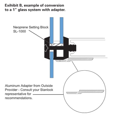 From a structural perspective, review of the existing glazing systems should be performed by a qualified Professional Engineer to determine if the lock-strip gasket curtain wall system may be remedially engineered and modified to accept standard one-inch nominal insulating glass units. This is critical since the addition of the IGU may require modification of the existing aluminum framing and system anchorage. Generally, the introduction of an IGU in a lock-strip glazing system will require additional support of the gasket body to accommodate the increased profile depth and weight of the glass. (Fig. 5)
The remedial designer should also determine if the depth of the existing aluminum framing members will meet current code and load requirements. Depending on the significance of the elements of the system to remain or be changed, the project may or may not be subjected to the same code requirements as a full facade replacement. Code and engineering reviews/evaluations should be performed to determine these requirements during the remedial project design phase.
With the introduction of insulating glass, the rubber and glass tolerance becomes of critical importance to the performance of the new glazing system. Care in specifying the design dimensions of the gasket system must be taken to ensure not only lip pressure for air and water penetration resistance, but also main body dimensions for structural performance such as roll off resistance.
Another critical consideration to anticipate is that IGU glazing in lock-strip gasket systems requires the gasket system to weep moisture from the glazing pocket to the exterior. This is not always the case when monolithic glass is used. The introduction of weeps to the original glazing rough opening conditions may prove problematic depending on the surrounding conditions.
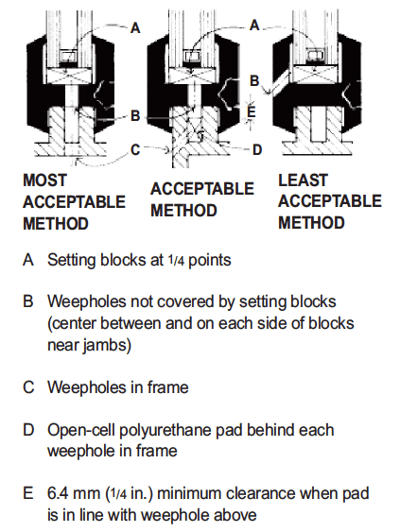 The preferred method of weeping lock-strip gaskets, in accordance with ASTM C964, is through the bottom of gasket glazing pockets into weepholes at the metal perimeter frame below. This location is often where existing perimeter weather seal joints or other interfaces with adjacent air and weather barriers are located. The standard does allow for weeping of the gasket through the vertical flange, however, this method is not preferable since the weeps are not protected and can conceivably allow water to enter from the exterior under conditions of differential pressure. (Fig. 6)
REGLAZING WITH VIG
As discussed, the introduction of an insulating glass unit as part of a lock-strip gasket replacement and reglazing project for a building previously equipped with monolithic glass has distinct benefits and challenges. The challenges faced by modification of the system to accommodate the increased weight of the IGU and new gasket profile to accept the IGU are one of the major disadvantages of engaging in this sort of remedial project, and they have the potential to greatly increase the cost of the project.
Advancements in the technology of vacuum insulating glass (VIG) offer a promising solution to the IGU reglazing challenges, and the product offers superior energy performance over traditional dual-pane insulating glass units.
VIG has a weight similar to monolithic glass of the same thickness. This is a considerable advantage for lock-strip gasket systems. With VIG the remedial project may be able to employ a new gasket similar to the original project lock-strip gasket die, as well as avoid modification of the system structurally.
The benefits of employing a VIG system should be evaluated as part of the overall remedial project. While VIG offers increased performance over IGU and may alleviate some need for engineering and system modification, the cost of VIG may be prohibitive to the project. Although the technology is not new, there has only been limited use of VIG in commercial glazing applications. As the VIG technology becomes more commercially available and accepted, the products should become more viable as a solution.
CONCLUSION
Mid-century lock-strip facade buildings can continue to function and even perform better with retrofit technology. By maintaining the lock-strip gaskets and upgrading glazing when possible, building performance can be increased and the service life of the building facade can be extended.
There are several options available to achieve a broad range of remediation goals that can be fit to any project or budget. With consideration to available products and emerging technology, lock-strip gasket system architecture can be preserved as a functional facade system well into the future.
Although there are challenges to these projects, the base of knowledge relating to lock-strip gasket glazing is large and well established. The ASTM standards C542, C716 and C964 are a valuable resource for anyone undertaking a lock-strip gasket remediation. These should be referenced and understood alongside of the manufacturer’s technical documentation and the applicable IGMA and RMA standards to ensure a successful project.

Michael Plewacki joined Morrison Hershfield in 2014 and currently serves as Principal/Façade Engineering Manager. Morrison Hershfield provides integrated solutions to residential, institutional, industrial and commercial clients who require reliable and cost-effective systems in both new and retrofit facilities. The combined skills of their engineers, architects, technicians and support personnel with diverse backgrounds in design and construction provide clients with a team recognized as leaders in the field of building science.
Mr. Plewacki can be reached at mplewacki@morrisonhershfield.com